

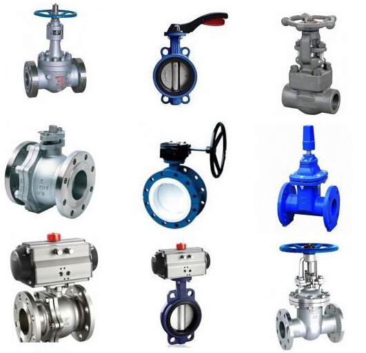

In the fluid piping system, the valve is the control element, and its main function is to isolate the equipment and the piping system, adjust the flow, prevent back-flow, regular and drain the pressure. It can be used to control the flow of various types of fluids such as air, water, steam, various corrosive media, mud, oil, liquid metal and radioactive media. Since it is very important to choose the most suitable valve for the piping system, it is also important to understand the characteristics of the valve and the steps and basis for selecting the valve.
Valve classification
1. The valve can be divided into two categories:
The first type is automatic valve: a valve that relies on the ability of the medium (liquid, gas) to act on its own.
Such as check valves, safety valves, regulating valves, traps, pressure reducing valves, etc.
The second type is drive valve: a valve that is operated manually, electrically, hydraulically, and pneumatically.
Such as gate valve, globe valve, throttle valve, butterfly valve, ball valve, plug valve, etc.
2. According to the structural features and basing on the moving direction of the closing piece relative to the valve seat, it can be divided into:
1. Sectional shape: the closing piece moves along the center of the valve seat;
2. Gate shape: The closing piece moves along the center of the vertical valve seat;
3. Cock and ball: The closing part is a plunger or ball, which rotates around its center line;
4. Swing shape: the closing piece rotates around the axis outside the valve seat;
5. Dish shape: the disc of the closing part, which rotates around the axis in the valve seat;
6. Slide valve shape: The closing piece slides in the direction perpendicular to the channel.
3. According to the purpose, the valve can be divided into different uses:
1. Open/Cut off use: used to connect or cut off pipeline media, such as globe valves, gate valves, ball valves, butterfly valves, etc.
2. Check use: used to prevent the medium from flowing back, such as a check valve.
3. Adjustment: used to adjust the pressure and flow of the medium, such as regulating valves and pressure reducing valves.
4. Distribution: used to change the flow direction of the medium and distribute the medium, such as three-way cock, distribution valve, slide valve, etc.
5. Safety valve: When the pressure of the medium exceeds the specified value, it is used to discharge excess medium to ensure the safety of the pipeline system and equipment, such as safety valves and emergency valves.
6. Other special purposes: such as traps, vent valves, drain valves, etc.
4. According to the driving mode, it can be divided into different driving modes:
1. Manual: With the help of hand-wheel, handle, lever or sprocket, etc., it is driven by manpower, and the transmission torque is equipped with worm gear, gear and other speed reduction devices.
2. Electric: driven by a motor or other electrical devices.
3. Hydraulic: driven by (water, oil).
4. Pneumatic: driven by compressed air.
5. According to the pressure, it can be divided according to the nominal pressure of the valve:
1. Vacuum valve: a valve with an absolute pressure of <0.1Mpa that is 760mm mercury column height, usually expressed in mm mercury column or mm water column.
2. Low pressure valve: valve with nominal pressure PN≤1.6Mpa (including steel valve with PN≤1.6MPa)
3. Medium pressure valve: a valve with a nominal pressure of PN2.5—6.4MPa.
4. High-pressure valve: a valve with a nominal pressure of PN10.0-80.0MPa.
5. Ultra-high pressure valve: a valve with a nominal pressure of PN≥100.0MPa.
6. According to the temperature of the medium, it can be divided according to the temperature of the medium when the valve is working:
1. Ordinary valve: suitable for valves with medium temperature -40℃~425℃.
2. High temperature valve: suitable for valves with a medium temperature of 425°C to 600°C.
3. Heat-resistant valve: suitable for valves with medium temperature above 600℃.
4. Low temperature valve: suitable for valves with medium temperature -150℃~-40℃.
5. Ultra-low temperature valve: suitable for valves whose medium temperature is below -150℃.
7. According to the nominal diameter and basing on the nominal diameter of the valve:
1. Small diameter valve: the valve with nominal diameter DN<40mm.
2. Medium-caliber valves: valves with a nominal diameter of DN50~300mm.
3. Large diameter valves: valves with a nominal diameter of DN350~1200mm.
4. Extra large diameter valves: valves with nominal diameter DN ≥ 1400mm.
8. According to the connection with the pipeline, it can be divided into:
1. Flange connection valve: The valve body has a flange and is connected to the pipeline by flange.
2. Threaded connection valve: the valve body has internal or external thread, and the valve is connected with the pipeline by thread.
3. Welding connection valve: The valve body has a welding port and is connected to the pipeline by welding.
4. Clamping clamp connection valve: a valve with clamps on the valve body and clamp connection with the pipeline.
5. Card sleeve connection valve: the valve is connected with the sleeve and pipe.
Valve characteristics
There are generally two types of valve characteristics, using characteristics and structural characteristics.
Using characteristics: It determines the main performance and scope of use of the valve. The characteristics of the valve are: valve category (closed circuit valve, regulating valve, safety valve, etc.), product type (gate valve, globe valve, butterfly valve, ball valve, etc.), material of the main parts of the valve (valve body, bonnet, valve stem, valve disc, sealing surface) and valve transmission mode, etc.
Structural characteristics: It determines some structural characteristics of the valve installation, repair, maintenance and other methods. The structural characteristics include: the structural length with overall height of the valve, the connection form with the pipeline (flange connection, threaded connection, clamp connection , External thread connection, welding end connection, etc.), the form of the sealing surface (inlay ring, thread ring, surfacing, spray welding, valve body), and valve stem structure (rotating rod, lifting rod), etc.
Steps and basis for selecting valves
Selection steps:
1. To clarify the purpose of the valve in the equipment or device, and determine the working conditions of the valve: applicable medium, working pressure, working temperature, etc.
2. To determine the nominal diameter and connection method of the pipe connected to the valve: flange, thread, welding, etc.
3. To determine the way to operate the valve: manual, electric, electromagnetic, pneumatic or hydraulic, electrical linkage or electrohydraulic linkage, etc.
4. To determine the material of the selected valve housing and internal parts according to the medium, working pressure and working temperature conveyed by the pipeline: gray cast iron, malleable cast iron, ductile iron, carbon steel, alloy steel, stainless acid-resistant steel, copper alloy, etc.
5. To choose the type of valve: closed circuit valve, regulating valve, safety valve, etc.
6. To determine the valve type: gate valve, globe valve, ball valve, butterfly valve, throttle valve, safety valve, pressure reducing valve, steam trap, etc.
7. To determine the parameters of the valve: For automatic valves, first determine the allowable flow resistance, discharge capacity, back pressure, etc., according to different needs, and then determine the nominal diameter of the pipeline and the diameter of the valve seat hole.
8. To determine the geometric parameters of the selected valve: structural length, flange connection form and size, valve height dimension after opening and closing, connecting bolt hole size and number, overall valve outline size, etc.
9. To use existing information: valve product catalog, valve product samples, etc. to select appropriate valve products.

Basis for selecting valve:
While understanding and mastering the steps of selecting valves, you should also further understand the basis for selecting valves.
1. The purpose, operating conditions and operating control methods of the selected valve.
2. The nature of the working medium: working pressure, working temperature, corrosion performance, whether it contains solid particles, whether the medium is toxic, whether it is a flammable or explosive medium, the viscosity of the medium, etc.
3. Requirements for valve fluid characteristics: flow resistance, discharge capacity, flow characteristics, sealing level, etc.
4. Requirements for installation dimensions and external dimensions: nominal diameter, connection to the pipeline and connection dimensions, external dimensions or weight restrictions, etc.
5. Additional requirements for the reliability and service life of valve products and the explosion-proof performance of electric devices.
Attention should be paid when selecting parameters:
If the valve is to be used for control purposes, the following additional parameters must be determined: operating method, maximum and minimum flow requirements, pressure drop for normal flow, pressure drop when closed, and maximum and minimum inlet pressure of the valve.
According to the above-mentioned basis and steps for selecting the valve, the internal structure of various types of valves must be understood in detail when selecting the valve reasonably and correctly, so that the correct choice can be made on the preferred valve.
The ultimate control of the pipeline is the valve. The valve opening and closing parts control the flow mode of the medium in the pipeline. The shape of the valve flow channel makes the valve have a certain flow characteristic. This must be considered when selecting the most suitable valve for the pipeline system.
Principles to be followed when selecting valves
1. Valves for shut-off and open media
The flow channel is a straight-through valve, and its flow resistance is small, and it is usually selected as a valve for shut-off and open medium. The downward closing valve (stop valve, plunger valve) is less used because of its tortuous flow path and higher flow resistance than other valves. Where higher flow resistance is allowed, a closed valve can be used.
2. Valves for flow control
Usually choose the valve that is easy to adjust the flow as the control flow. Downward closing valves (such as globe valves) are suitable for this purpose because the size of its seat is proportional to the stroke of the closing piece. Rotary valves (plug valves, butterfly valves, ball valves) and flex-body valves (pinch valves, diaphragm valves) can also be used for throttling control, but they are usually only applicable within a limited range of valve diameters. The gate valve uses a disc-shaped gate to cross-cut the circular valve seat port. It can only control the flow better when it is close to the closed position, so it is usually not used for flow control.
3. Valves for reversing and shunting
According to the needs of reversing and shunting, this valve can have three or more channels. Plug valves and ball valves are more suitable for this purpose. Therefore, most of the valves used for reversing and splitting select one of these valves. But in some cases, other types of valves can also be used for reversing and shunting as long as two or more valves are properly connected to each other.
4. Valves for media with suspended particles
When there are suspended particles in the medium, it is most suitable to use a valve with a wiping effect on the sliding of the closing member along the sealing surface. If the back and forth movement of the closing piece to the valve seat is vertical, it may hold particles. Therefore, unless the sealing surface material allows particles to be embedded, this valve is only suitable for basic clean media. Ball valves and plug valves have a wiping effect on the sealing surface during the opening and closing process, so they are suitable for use in media with suspended particles.

Instructions of valve selection
1. Selection of gate valve
In general, gate valves should be preferred. In addition to suitable for steam, oil and other media, gate valves are also suitable for media containing granular solids and high viscosity, and are suitable for valves in venting and low vacuum systems. For media with solid particles, the valve body of the gate valve should have one or two purge holes. For low-temperature media, low-temperature dedicated gate valves should be used.
2. Instructions for selection of globe valve
The stop valve is suitable for pipelines that do not require strict fluid resistance, that is, the pressure loss is not considered. The pipelines or devices for high temperature and high pressure media are suitable for medium pipelines such as steam with DN<200mm. Small valves can choose globe valves, such as needle valves, instrument valves, sampling valves, pressure gauge valves, etc.. Globe valves have flow regulation or pressure regulation, but do not require high adjustment accuracy, and the diameter of the pipeline is relatively small, so globe valves or throttling should be used. For highly toxic media, bellows-sealed globe valves should be used. However, globe valves should not be used for media with high viscosity and media containing particles that are easy to precipitate, nor should they be used as vent valves and valves for low vacuum systems.
3. Description of ball valve selection
The ball valve is suitable for low temperature, high pressure and high viscosity medium. Most ball valves can be used in media with suspended solid particles, and can also be used in powder and granular media according to the material requirements of the seal. Full-channel ball valves are not suitable for flow adjustment, but are suitable for occasions that require fast opening and closing, and are easy to implement emergency cut-off in case of accident. Usually it is recommended in pipelines with strict sealing performance, abrasion, narrowing channels, rapid opening and closing actions, high pressure cut-off (large pressure difference), low noise, vaporization, small operating torque, and small fluid resistance. Use ball valves. Ball valves are suitable for light structure, low pressure cut-off, and corrosive media. Ball valves are also the most ideal valve for low temperature and cryogenic media. For low temperature media piping systems and devices, low temperature ball valves with bonnets should be used. The seat material of the floating ball valve should bear the load of the ball and the working medium. The large-diameter ball valve requires a greater force during operation. The DN≥200mm ball valve should use the worm gear transmission form; the fixed ball valve is suitable for larger diameter and high pressure occasions; in addition, ball valves used for process highly toxic materials and flammable medium pipelines should have a fireproof and anti-static structure.
4. Description of throttle valve selection
The throttle valve is suitable for occasions where the medium temperature is low and the pressure is high, and it is suitable for the parts that need to adjust the flow and pressure. It is not suitable for the medium with high viscosity and containing solid particles, and it is not suitable for the isolation valve.
5. Description of plug valve selection
The plug valve is suitable for occasions requiring fast opening and closing. Generally, it is not suitable for steam and higher temperature media, for lower temperature and high viscosity media, and also for media with suspended particles.
6. Description of butterfly valve selection
Butterfly valve is suitable for large diameter (such as DN﹥600mm) and short structure length, as well as occasions where flow adjustment and fast opening and closing are required. Generally used for water, oil and compression with temperature ≤80℃ and pressure ≤1.0MPa Air and other media; because the pressure loss of butterfly valves is relatively large compared with gate valves and ball valves, butterfly valves are suitable for pipeline systems with less stringent pressure loss requirements.
7. Check valve selection instructions
Check valves are generally suitable for clean media, not for media containing solid particles and high viscosity. When DN≤40mm, lift check valve should be used (only allowed to be installed on horizontal pipelines); when DN=50~400mm, swing check valve should be used (can be installed on both horizontal and vertical pipelines, If installed on a vertical pipeline, the flow direction of the medium should be from bottom to top); when DN≥450mm, a buffer check valve should be used; when DN=100~400mm, a wafer check valve can also be used; swing check valve The return valve can be made into a very high working pressure, PN can reach 42MPa, and can be applied to any working medium and any working temperature range according to the material of the shell and the seal. The medium is water, steam, gas, corrosive medium, oil, medicine, etc. The working temperature range of the medium is between -196~800℃.
8. Diaphragm valve selection instructions
Diaphragm valve is suitable for oil, water, acidic medium and medium containing suspended solids whose working temperature is less than 200℃ and pressure is less than 1.0MPa. It is not suitable for organic solvent and strong oxidant medium; weir type diaphragm valve should be selected for grinding granular medium. The selection of weir type diaphragm valve should refer to its flow characteristics table; viscous fluid, cement slurry and sedimentary medium should use straight-through diaphragm valve; except for specific requirements, diaphragm valve is not suitable for vacuum pipelines and vacuum equipment.
Valve applications, operating frequencies, and services are ever-changing. To control or eliminate even low-level leakage, the most important and critical equipment is the valve. It is important to learn to choose the valve correctly.